Smart Bladeless Fan
This graduate independent project utilizes 3D printing, laser cutting, and Arduino technology to develop a safe, quiet bladeless fan tailored for STEAM learning environments. It features an intuitive interface controlled by a potentiometer and buttons, providing a tactile, interactive hardware experience.
Key Features
- 3D printed aerodynamic structure
- Arduino-controlled motor and interface
- Laser-cut protective circuit base
- Multi-modal LED light displays
- Integrated tactile potentiometer controls
- Built-in musical audio mode
Technical Specifications
Introduction
This graduate project aims to design and develop an innovative bladeless fan that can be controlled by Potentiometer and Buttons. The bladeless fan will incorporate digital fabrication technologies (3D printing and Laser Cutting) and Arduino development. Noticeably, Despite being labeled as a bladeless fan, this project incorporates a hidden blade housed within the fan body. However, the hidden blade is tiny and does not generate substantial noise.
Learning Purpose for STEAM
This project revolves around technology, aligning with STEAM Learning principles and offering educational potential in the realm of health. The demand for bladeless fans has surged due to their capacity to mitigate risks posed to children and adults by traditional fans with sharp blades—accidental contact with these fans can lead to injuries. Additionally, bladeless fans significantly diminish noise levels, fostering improved learning environments in classrooms, offices, and meeting rooms.
Moreover, Bladeless fans can contribute to STEAM (Science, Technology, Engineering, Arts, and Mathematics) learning in various ways:
- Engineering Design: Building a bladeless fan involves designing intricate components that utilize air dynamics, aerodynamics, and structural engineering principles. Students can learn about fan construction, materials, and the mechanics behind bladeless technology.
- Technology Integration: Understanding the technology behind bladeless fans involves studying the functioning of motors, sensors, and airflow control systems. This provides hands-on experience with electrical components and programming (if the fan is automated).
- Science of Airflow: Exploring the science behind airflow patterns and air circulation is essential in bladeless fan design. It involves studying Bernoulli’s principle, air pressure differentials, and how these principles apply to create a smooth, bladeless airflow.
- Innovation and Problem-Solving: Encouraging innovation by exploring alternative fan designs. This prompts students to think critically, experiment with new ideas, and troubleshoot challenges in creating effective, bladeless cooling solutions.
- Health and Safety Awareness: Highlighting the safety benefits of bladeless fans compared to traditional fans with exposed blades. Understanding how technology can mitigate potential hazards in daily life fosters an appreciation for safety measures.
- Environmentally Friendly Design: Discussing the energy efficiency and eco-friendly aspects of bladeless fans. Exploring ways to make cooling solutions more sustainable aligns with environmental sciences and studies.
By integrating these aspects into educational modules or projects, bladeless fans can serve as a tangible and engaging entry point for students to delve into various disciplines within the STEAM framework.
Inspiration
The inception of this project draws inspiration from an amalgamation of innovative 3D Printed Portable Bladeless Fan projects, each offering unique insights and creative approaches:
- Hackaday’s Affordable Bladeless Fan: The Hackaday project (https://hackaday.com/2020/09/01/this-3d-printed-bladeless-fan-gets-it-done-cheap/) serves as a cornerstone, showcasing an affordable and functional 3D-printed bladeless fan design. Its emphasis on cost-effectiveness and functionality sparked the initial idea.
- Thingiverse’s Design Repository Exploring Thingiverse’s repository (https://www.thingiverse.com/thing:1645081) unearthed a wealth of diverse bladeless fan designs, offering a spectrum of creative possibilities and serving as a catalyst for innovative ideation.
- Yanko Design’s Iconic Bladeless Fan Concept: Yanko Design’s conceptualization (https://www.yankodesign.com/2019/02/07/you-can-now-3d-print-your-own-iconic-bladeless-fan/) of an iconic bladeless fan provided a visionary perspective, influencing the aesthetic and functional aspects of the project.
These projects, alongside insightful resources from Instructables (https://www.instructables.com/3D-Printed-Portable-Bladeless-Fan/ and https://www.instructables.com/DIY-Bladeless-Fan-From-Scratch/ ) and a comprehensive YouTube demonstration (https://www.youtube.com/watch?v=hbCsDYLP6vA ), collectively sparked the idea and provided a diverse array of methodologies, designs, and concepts. This accumulation of innovative endeavors served as the catalyst for this project’s inception, fostering creativity and pushing the boundaries of traditional fan design.
3D Printing Elements
I employed 3D printing technology to create a fan. This fan was designed in the shape of a modern bladeless fan. It was attached with the laser cut box from the bottom and can stand on a desk. The 3D fan structure is comprised of five components: Inner Circular Fan Head, Outer Circular Fan Head, Circular Fan Boddy, Hidden Blade and DC Motor Holder. The five components were crafted using 3D design in the Fusion360 software, refined with the Prusa Slicer tool, and then printed using a Prusa i3 MK3 printer at the UNCC CCI Makerspace.
3D Modeling in Fusion 360
Inner Circular Fan Head
Purpose: The inner circular fan head is crafted to merge with the outer circular fan, constructing the overall fan head. This union results in the formation of a confined circular space facilitating the flow of air. Originally conceived by Elite Worm and featured in their earlier model (https://hackaday.com/2020/09/01/this-3d-printed-bladeless-fan-gets-it-done-cheap/), I have adjusted its dimensions to correspond with the specifications and objectives of my unique project design.
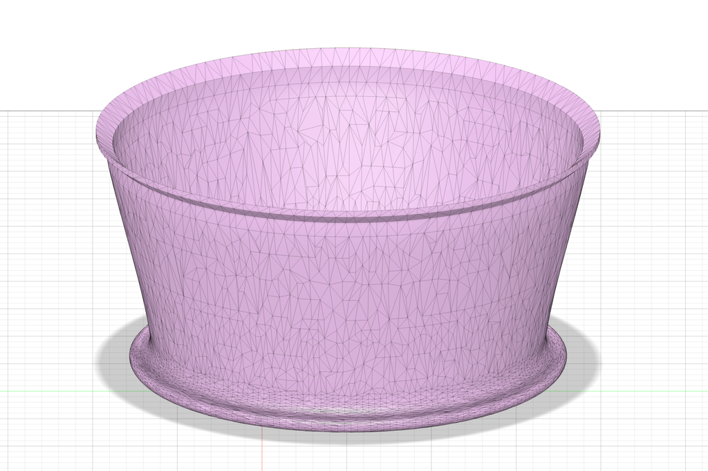
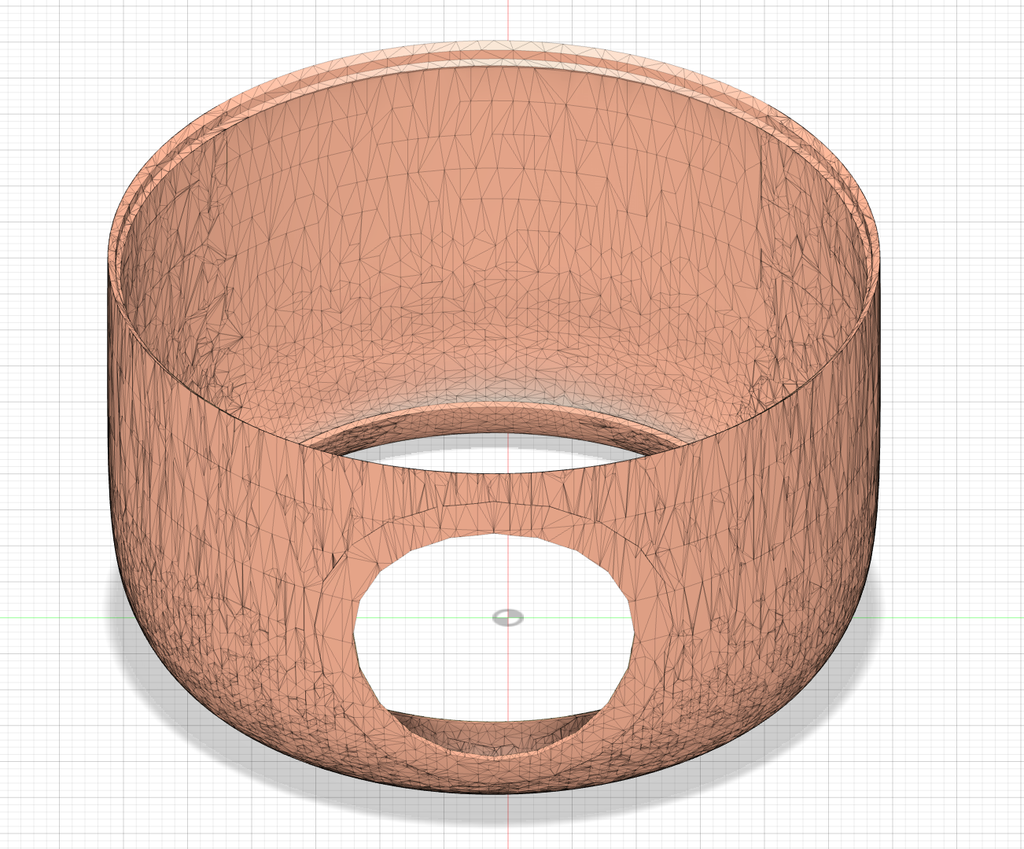
Outer Circular Fan Head
Purpose: The external circular fan head is engineered to merge with the inner circular fan, creating a cohesive fan assembly. This amalgamation results in the creation of a confined circular space facilitating the flow of air. Originally conceptualized by Elite Worm and showcased in their prior model (https://hackaday.com/2020/09/01/this-3d-printed-bladeless-fan-gets-it-done-cheap/), I have tailored its dimensions to align with the specifications and intentions of my personal project design.
Circular Fan Body
Purpose: The fan body serves as a connecting element between the fan head and the laser-cut box housing the Arduino circuit. Within the Circular Fan Body, there resides a hidden blade and DC Motor holder. It features the surrounding openings that facilitate the inflow of air while the hidden blade is in motion.
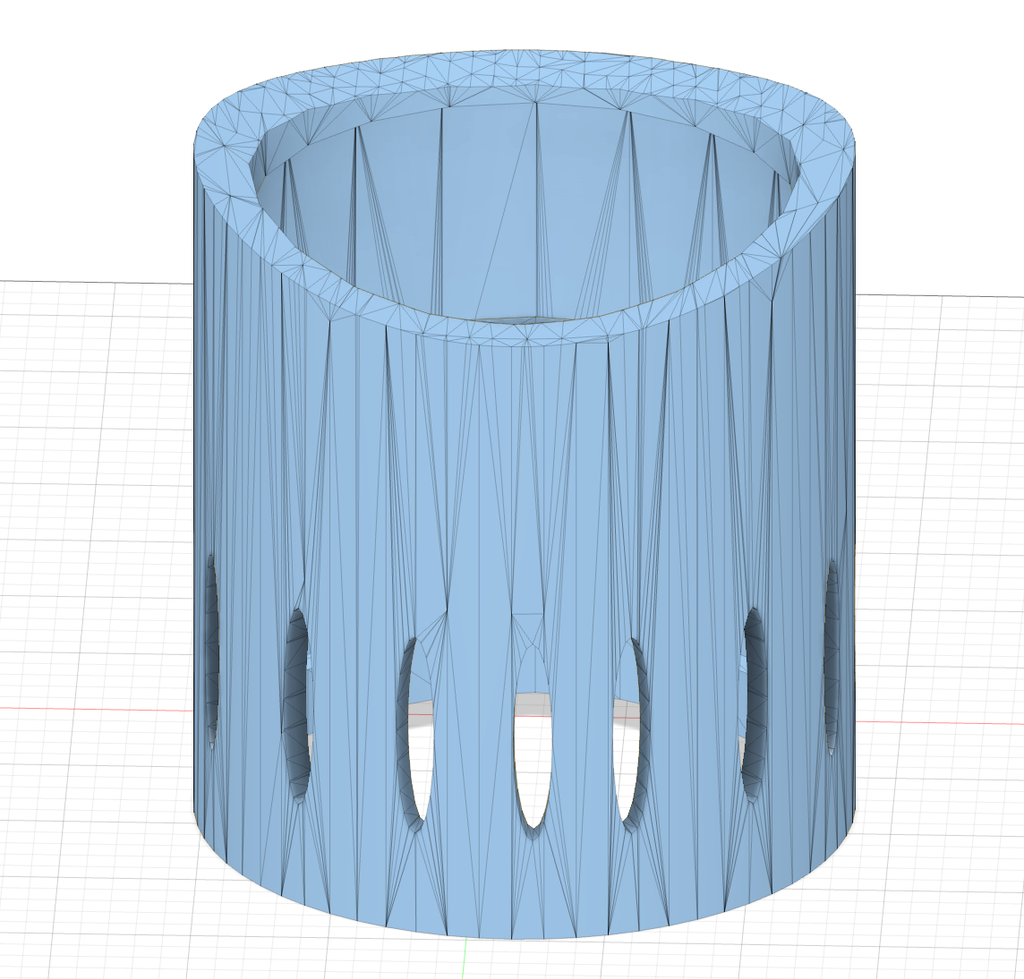
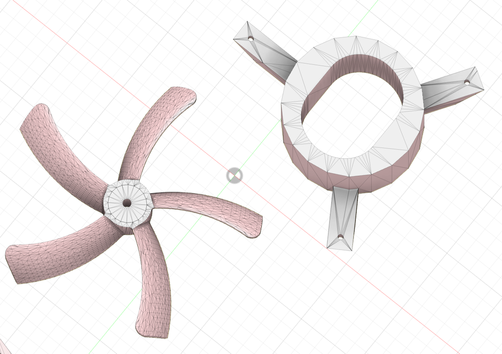
Hidden Blade & DC Motor Holder
Purpose: Despite being labeled as a bladeless fan, this project incorporates a hidden blade housed within the fan body. The hidden blade is tiny and does not generate substantial noise. The DC Motor Holder is responsible for securing both the DC Motor and the Hidden Blade, ensuring the blade’s central alignment to prevent damage resulting from imbalance.
Printed Structural Components

3D Printed Fan Elements Before Assembly
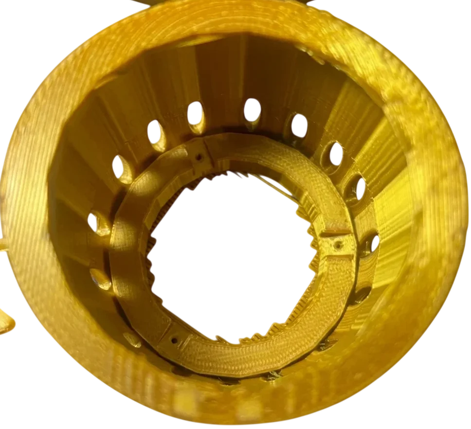
3D Printed Circular Fan Body
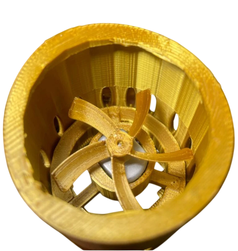
3D Printed Circular Fan Body, Hidden Blade and DC Motor Holder After Assembly
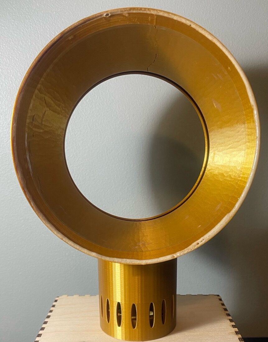
3D Printed Fan Elements After Assembly
Laser Cutting Element
An integral laser-cut component within this project is the six-sided Box. This box serves as the storage unit for the Arduino circuits and acts as a stable base for the Fan. On its top surface, there will be a vector cut hole allowing wiring connections for the DC Motor and RGB LED from the Circular Fan Body to link up with the Arduino circuit in the Laser Cut Box. The underside of the box will showcase intricate raster designs, presenting the Fan’s designated name, “Tann’s Bladeless Fan,” alongside a distinctive signature. The front panel combines raster elements containing the names of three modes (Fan, Light, and Music) and vector elements in the form of square hole, designed to accommodate two switches and a potentiometer. The remaining three sides of the box maintain plain, unembellished surfaces.
Laser Cut Design in Inkscape
Method & Purpose: The box was crafted using the Inkscape software, drawing inspiration from the small laser cut box project I had previously undertaken. I modified the original design into a notched box style, enlarging it to accommodate the physical Arduino circuit. The box was edited by Adobe Illustrator software and printed by the laser cutting Mini printer at the UNCC CCI Makerspace.
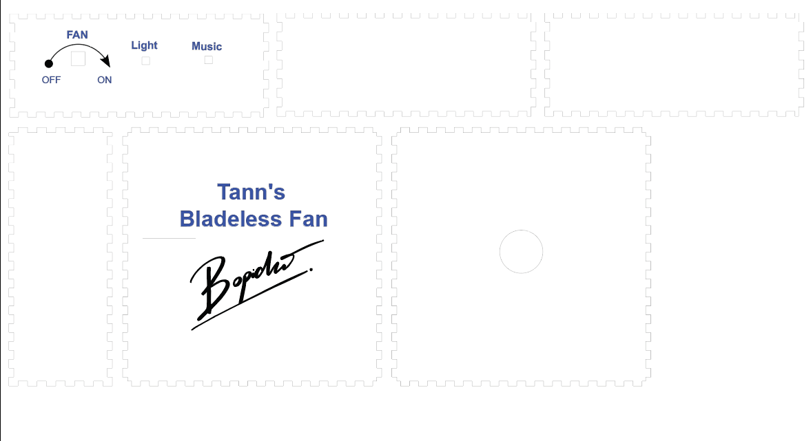
Laser Cut Project Components:
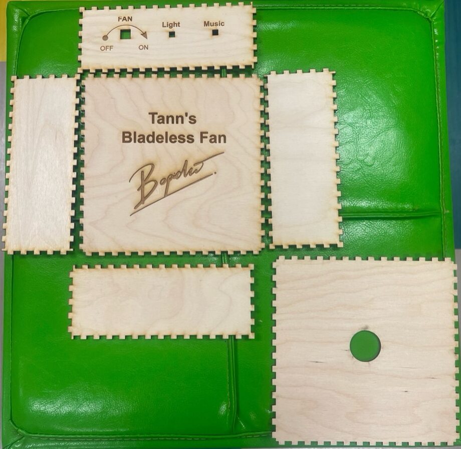
Laser Cut Box Before Assembly
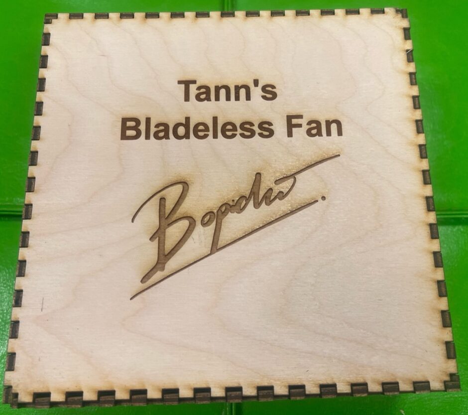
Laser Cut Box Before Assemble (Bottom View)
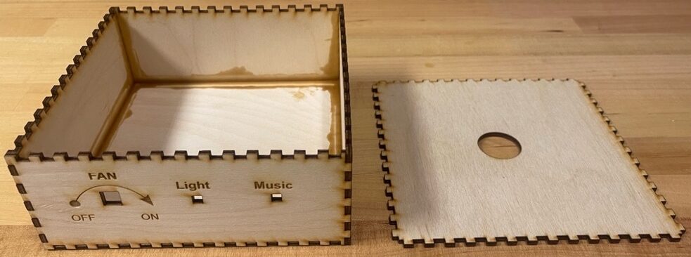
Laser Cut Box After Assembly (Top and Side View)
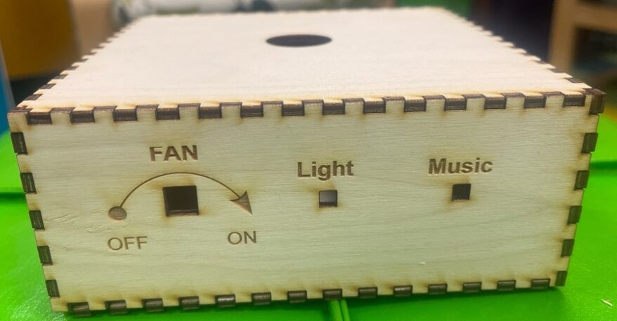
Laser Cut Box After Assembly
Arduino Elements:
For the incorporation of Arduino into this project, the three interactions are outlined as follows:
- First Interaction: Activation occurs when the user rotate the Potentiometer to turn the fan.
- Second Interaction: Activation occurs when the user presses the middle switch/button to initiate Light Mode and lights up the multi-colored LED inside the Circular Fan Body. The RGB LED will exhibit various colors as the user continues to press the switch/button.
- Third Interaction: Activation is triggered when the user presses the right switch/button, which activates the Music Mode.
- Arduino Inputs: Arduino board, Two Breadboard, USB Cable, Barrel Jack Cable, 9V battery, Potentiometer, 2 Snap Buttons/Switches, Resistors, and jumper wire kits
- Arduino Outputs: DC Motor, Multi-colored LED (RGB LED), and Speaker
Arduino Source Code
• #define NOTE_B0 31

• #define NOTE_C1 33

• #define NOTE_CS1 35

• #define NOTE_D1 37

• #define NOTE_DS1 39

• #define NOTE_E1 41

• #define NOTE_F1 44

• #define NOTE_FS1 46

• #define NOTE_G1 49

• #define NOTE_GS1 52

• #define NOTE_A1 55

• #define NOTE_AS1 58

• #define NOTE_B1 62

• #define NOTE_C2 65

• #define NOTE_CS2 69

• #define NOTE_D2 73

• #define NOTE_DS2 78

• #define NOTE_E2 82

• #define NOTE_F2 87

• #define NOTE_FS2 93

• #define NOTE_G2 98

• #define NOTE_GS2 104

• #define NOTE_A2 110

• #define NOTE_AS2 117

• #define NOTE_B2 123

• #define NOTE_C3 131

• #define NOTE_CS3 139

• #define NOTE_D3 147

• #define NOTE_DS3 156

• #define NOTE_E3 165

• #define NOTE_F3 175

• #define NOTE_FS3 185

• #define NOTE_G3 196

• #define NOTE_GS3 208

• #define NOTE_A3 220

• #define NOTE_AS3 233

• #define NOTE_B3 247

• #define NOTE_C4 262

• #define NOTE_CS4 277

• #define NOTE_D4 294

• #define NOTE_DS4 311

• #define NOTE_E4 330

• #define NOTE_F4 349

• #define NOTE_FS4 370

• #define NOTE_G4 392

• #define NOTE_GS4 415

• #define NOTE_A4 440

• #define NOTE_AS4 466

• #define NOTE_B4 494

• #define NOTE_C5 523

• #define NOTE_CS5 554

• #define NOTE_D5 587

• #define NOTE_DS5 622

• #define NOTE_E5 659

• #define NOTE_F5 698

• #define NOTE_FS5 740

• #define NOTE_G5 784

• #define NOTE_GS5 831

• #define NOTE_A5 880

• #define NOTE_AS5 932

• #define NOTE_B5 988

• #define NOTE_C6 1047

• #define NOTE_CS6 1109

• #define NOTE_D6 1175

• #define NOTE_DS6 1245

• #define NOTE_E6 1319

• #define NOTE_F6 1397

• #define NOTE_FS6 1480

• #define NOTE_G6 1568

• #define NOTE_GS6 1661

• #define NOTE_A6 1760

• #define NOTE_AS6 1865

• #define NOTE_B6 1976

• #define NOTE_C7 2093

• #define NOTE_CS7 2217

• #define NOTE_D7 2349

• #define NOTE_DS7 2489

• #define NOTE_E7 2637

• #define NOTE_F7 2794

• #define NOTE_FS7 2960

• #define NOTE_G7 3136

• #define NOTE_G7 3136
• #define NOTE_GS7 3322
• #define NOTE_A7 3520
• #define NOTE_AS7 3729
• #define NOTE_B7 3951
• #define NOTE_C8 4186
• #define NOTE_CS8 4435
• #define NOTE_D8 4699
• #define NOTE_DS8 4978
•
• // For 1st Arduino Interaction (FAN)
• const int MOTOR=9; //Motor on Digital Pin 9
• const int POT=1; //POT on Analog Pin A1
• int val = 0;
•
• // For 2nd Arduino Interaction (RGB LED)
• const int BUTTON2 = 2;
• const int GLED = 10;
• const int BLED = 11;
• const int RLED = 12;
• boolean lastButton2 = LOW;
• int ledMode = 0;
• unsigned long lastDebounceTime = 0;
• unsigned long debounceDelay = 80;
•
• // For 3rd Arduino Interaction (Music)
• const int BUTTON3 = 3;
• const int SPEAKER = 13;
• boolean lastButton3 = LOW;
• boolean isPlaying = false;
• unsigned long lastMelodyTime = 0;
•
• /// Note Array for "Jingle Bells"
• int notes[] = {
• NOTE_E4, NOTE_E4, NOTE_E4, NOTE_E4, NOTE_E4, NOTE_E4,
• NOTE_E4, NOTE_G4, NOTE_C4, NOTE_D4, NOTE_E4,
• NOTE_F4, NOTE_F4, NOTE_F4, NOTE_F4, NOTE_F4, NOTE_E4,
• NOTE_E4, NOTE_E4, NOTE_E4, NOTE_E4, NOTE_D4, NOTE_D4,
• NOTE_E4, NOTE_D4, NOTE_G4,
• NOTE_E4, NOTE_E4, NOTE_E4, NOTE_E4, NOTE_E4, NOTE_E4,
• NOTE_E4, NOTE_G4, NOTE_C4, NOTE_D4, NOTE_E4,
• NOTE_F4, NOTE_F4, NOTE_F4, NOTE_F4, NOTE_F4, NOTE_E4,
• NOTE_E4, NOTE_E4, NOTE_G4, NOTE_G4, NOTE_F4, NOTE_D4, NOTE_C4
• };
•
// The Duration of each note (in ms) for "Jingle Bells"
• int times[] = {
• 250, 250, 500, 250, 250, 500,
• analogWrite(MOTOR, val);
•
• // For 2nd Arduino Interaction (RGB LED)
• boolean currentButton2 = debounceButton(BUTTON2, lastButton2);
• if (lastButton2 == LOW && currentButton2 == HIGH) {
• if (millis() - lastDebounceTime > debounceDelay) {
• lastDebounceTime = millis();
• ledMode = (ledMode + 1) % 8;
• setMode(ledMode);
• }
• }
• lastButton2 = currentButton2;
•
• // For 3rd Arduino Interaction (Music)
• boolean currentButton3 = digitalRead(BUTTON3);
• if (currentButton3 == HIGH && lastButton3 == LOW) {
• // Reset button is pressed, play the melody again
• for (int i = 0; i < sizeof(notes) / sizeof(notes[0]); i++) {
• tone(SPEAKER, notes[i], times[i]);
• delay(times[i]);
• }
• }
•
• lastButton3 = currentButton3;
• }
•
• boolean debounceButton(int buttonPin, boolean last) {
• boolean current = digitalRead(buttonPin);
• if (last != current) {
• delay(5);
• current = digitalRead(buttonPin);
• }
• return current;
• }
Arduino Physical Circuit
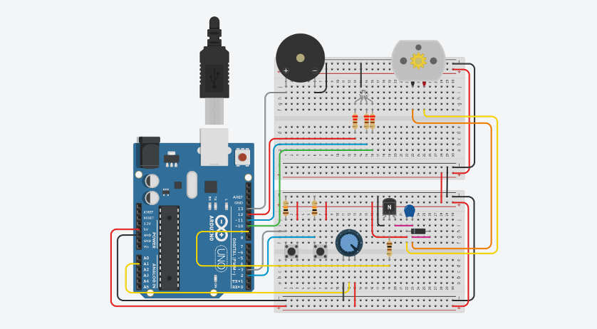
Arduino Prototyping in Tinkercad
Arduino Physical Circuit
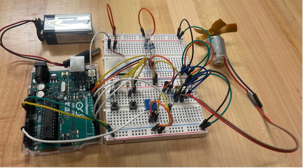
Arduino Physical Circuit Setup
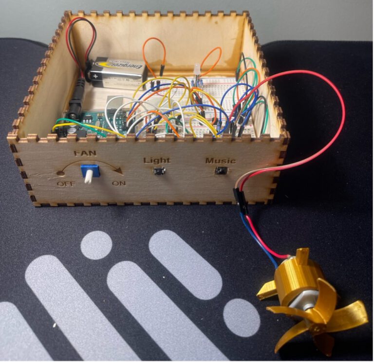
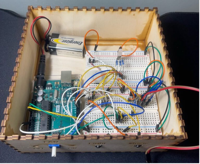
Arduino Physical Circuit Setup After Assembly in the Laser Cut Box
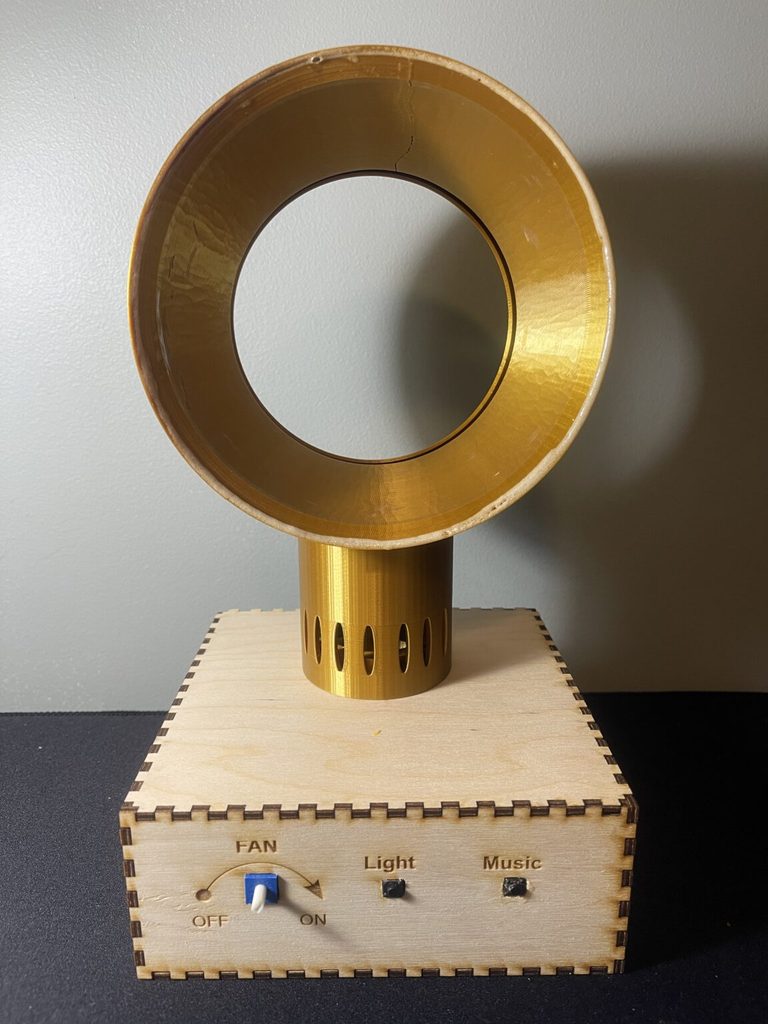
Combined Outcome of All Elements After Assembly
In Conclusion
The Smart Bladeless Fan project successfully merges safe, quiet cooling technology with the power of digital fabrication and Arduino programming. By providing a tangible platform for students to navigate engineering challenges and hardware logic, it serves as a robust STEAM learning tool for modern classrooms. Future iterations could explore automated environmental sensors or modular housing designs to further enhance its application in educational lab settings.
Download the Full Research Paper
Get the full PDF for technical specs, design files, and Arduino code for this fan.