RGB Lamp Box
The RGB Lamp Box is a graduate independent project that combines 3D printing, laser cutting, and Arduino-based electronics to create an interactive, color-changing lamp. The 3D‑printed frame and components form the lamp’s structure, while laser‑cut wooden panels complete the box design. Inside, an Arduino controls LEDs and a buzzer using custom code and prototyping in Tinkercad, enabling multiple lighting modes and responsive behavior. Together, these elements showcase an end‑to‑end design process from digital modeling and fabrication to circuit design and programming.
Key Features
- 3D printed aerodynamic structure
- Arduino-controlled motor and interface
- Laser-cut protective circuit base
- Multi-modal LED light displays
- Integrated tactile potentiometer controls
- Built-in musical audio mode
Technical Specifications
Introduction
This project centers around the creation of an innovative RGB lamp box that boasts not only color-changing functionalities but also incorporates musical tones to enhance user experience. The lamp box is designed to be hung by a 3D printed frame/hanger, adding unique and customizable lightings and audio elements to any environment.
3D Printing Elements
I employed 3D printing technology to create a frame/hanger specifically for a lamp. This hanger, designed in the shape of a house, serves as the supporting frame for the Laser Cut Cube Box. It can be mounted to the ceiling using either a string or a chain. The hanger is comprised of three components: the Lamp Box Header, which forms the roof; the Lamp Box Frame, acting as the body; and the Lamp Box Bottom, serving as the base. The three components were crafted using 3D design in the Fusion360 software, refined with the Prusa Slicer tool, and then printed using a Prusa i3 MK3 printer at the UNCC CCI Makerspace.
3D Modeling in Fusion 360
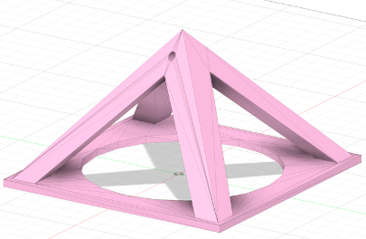
Lamp Box Header (Roof)
Purpose: Serving as the top cover for the Lamp Box Frame, it features a small aperture for ceiling mounting, either by a string or a chain. Additionally, there’s a bigger circular opening at the center bottom, revealing the interior of the lamp box, complete with raster designs including the lamp’s name, “Tann’s Lamp,” and a personalized signature.
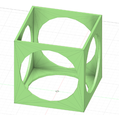
Lamp Box Frame
Purpose: Functioning as the main structure, this body frame features five large circular openings at the center of each of its five sides. These openings provide a view into the lamp box’s interior, which showcases both vector designs (featuring four tree vector cuts) and raster designs (featuring the name of the lamp, “Tann’s Lamp,” and a unique signature). The frame’s bottom side is designed to be open, enabling the Laser Cut Cube Box to slide in easily, and it can be securely closed using the Lamp Box Bottom (Base).
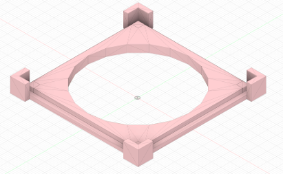
Lamp Box Bottom (Base)
Purpose: Acting as the foundation/base, this component is essential for closing the lamp box frame (Body). The base also features a large circular opening providing a clear view of the interior laser cut cube box and offering easy access to control the four switches located at the bottom.
3D Printed Project Components:
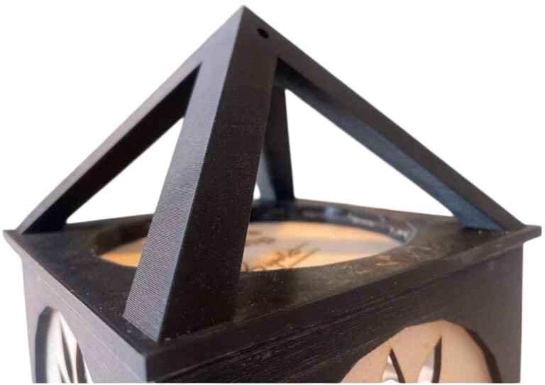
3D Printed Lamp Box Header (Roof)
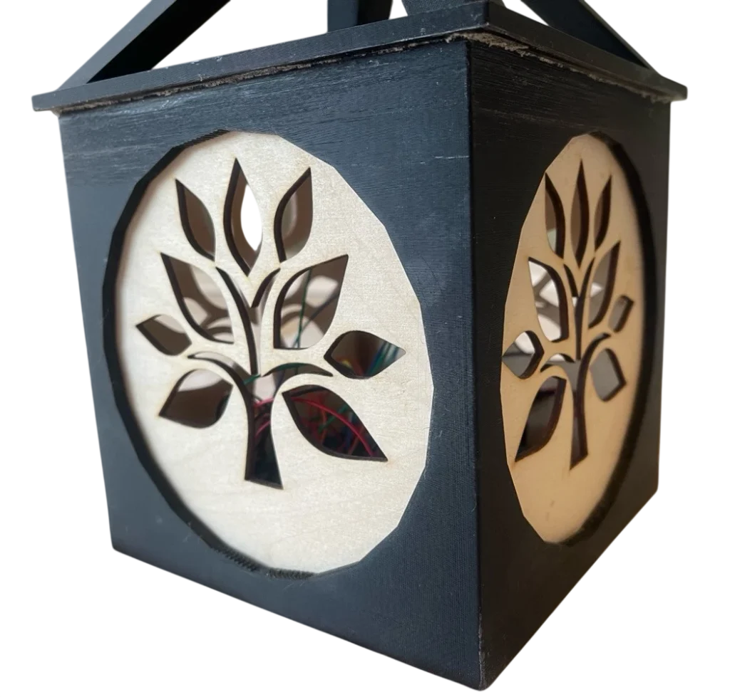
3D Printed Lamp Box Framer (Body)
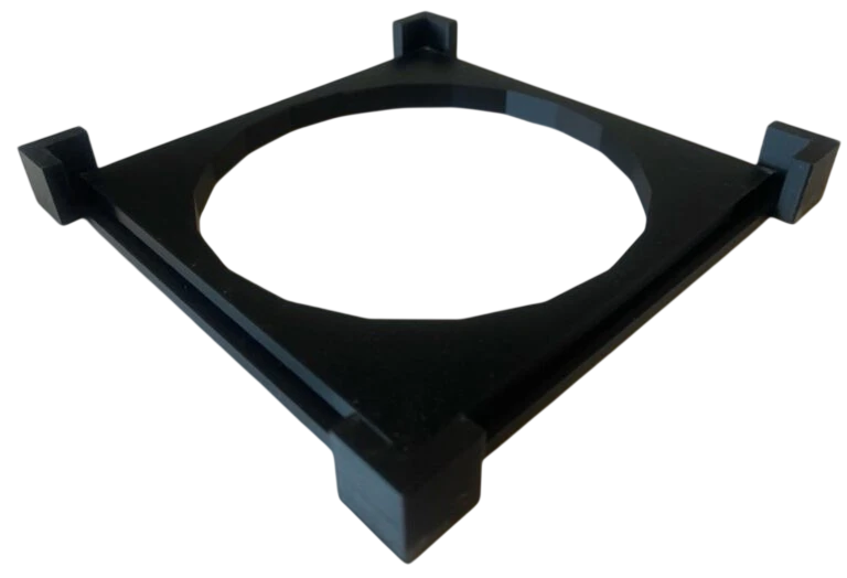
3D Printed Lamp Box Bottom (Base)
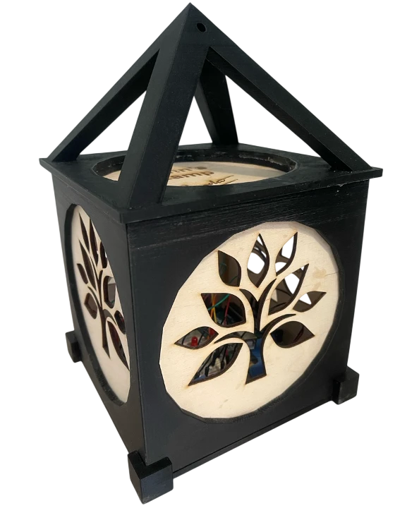
3D Printed Lamp Box Hanger After Assembly
Laser Cutting Element
The crucial laser-cut element in this project is a six-sided Cube Box. The top side of the box will feature a raster design displaying the lamp’s name, “Tann’s Lamp,” along with a signature. The bottom side combines raster elements, including the names of four modes, and vector elements, specifically square openings for fitting four switches. The remaining four sides of the cube incorporate vector designs with tree patterns, allowing light to emanate from within the lamp.
Laser Cut Design in Inkscape
- Method & Purpose: The cube box was crafted using the Inkscape software, drawing inspiration from the small laser cut box project I had previously undertaken. I modified the original design into a notched box style, enlarging it to accommodate the physical Arduino circuit. Additionally, I incorporated four square vector cuts at the bottom to fit four switches, along with raster elements depicting four different Modes. This cube box serves as an internal frame to house all the Arduino components, allowing light to shine through from within the lamp, creating beautiful patterns in the dark.
- The cube box was edited by Adobe Illustrator software and printed by the laser cutting Mini printer at the UNCC CCI Makerspace.
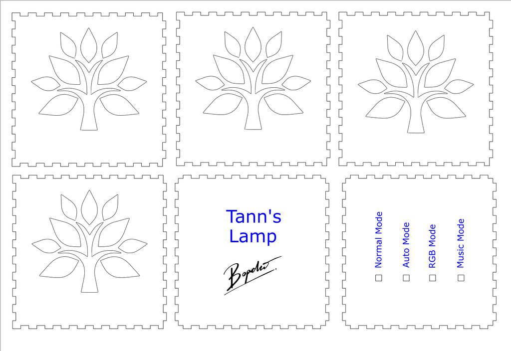
Laser Cut Project Components:
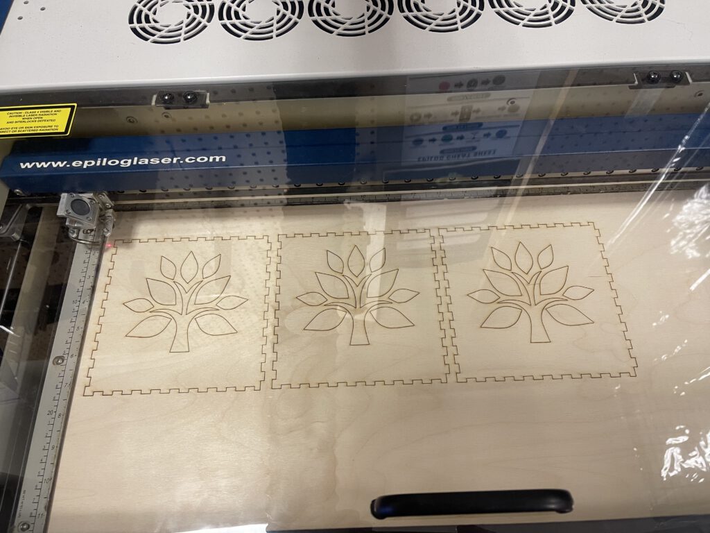
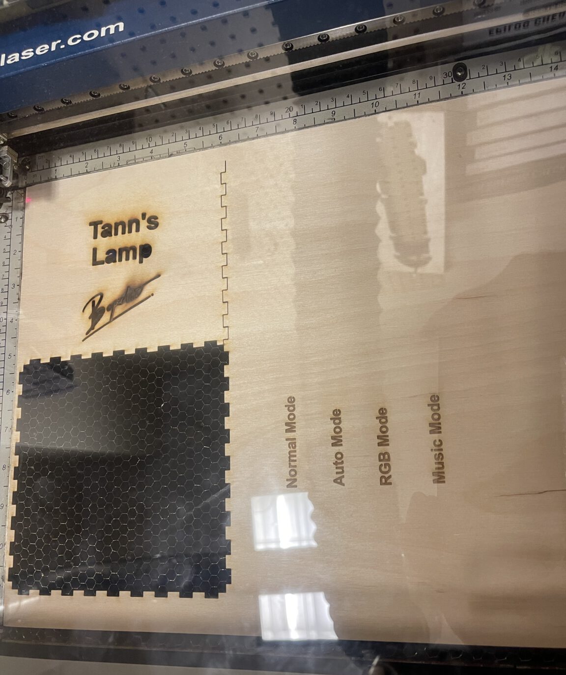
Laser Cutting Process using Wood as the material
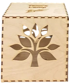
Laser Cut Box After Assembly
Arduino Elements:
For the incorporation of Arduino into this project, the four interactions are outlined as follows:
- First Interaction: Activation occurs when the user presses the 1st switch/button to initiate Normal Mode and illuminate the single-colored LED within the Laser Cut Cube Box.
- Second Interaction: Activation occurs when the user presses the 2nd switch/button to initiate Auto Mode and illuminate another single-colored LED which can be adjusted by brightness of the environment through Light sensor.
- Third Interaction: Activation is triggered when the user presses the 3rd switch or button, which activates the RGB Mode and lights up the multi-colored LED inside the Laser Cut Cube Box. The RGB LED will exhibit various colors as the user continues to press the third switch or button.
- Fourth Interaction: Activation is triggered when the user presses the 4th switch or button, which activates the Music Mode.
- Arduino Inputs: Arduino board, Two Breadboard, USB Cable, Barrel Jack Cable, 5V battery, Light sensor, 4 Snap Buttons/Switches, Resistors, and jumper wire kits
- Arduino Outputs: Single-colored LED, Multi-colored LED (RGB LED), Speaker
Arduino Source Code
• #define NOTE_B0 31

• #define NOTE_C1 33

• #define NOTE_CS1 35

• #define NOTE_D1 37

• #define NOTE_DS1 39

• #define NOTE_E1 41

• #define NOTE_F1 44

• #define NOTE_FS1 46

• #define NOTE_G1 49

• #define NOTE_GS1 52

• #define NOTE_A1 55

• #define NOTE_AS1 58

• #define NOTE_B1 62

• #define NOTE_C2 65

• #define NOTE_CS2 69

• #define NOTE_D2 73

• #define NOTE_DS2 78

• #define NOTE_E2 82

• #define NOTE_F2 87

• #define NOTE_FS2 93

• #define NOTE_G2 98

• #define NOTE_GS2 104

• #define NOTE_A2 110

• #define NOTE_AS2 117

• #define NOTE_B2 123

• #define NOTE_C3 131

• #define NOTE_CS3 139

• #define NOTE_D3 147

• #define NOTE_DS3 156

• #define NOTE_E3 165

• #define NOTE_F3 175

• #define NOTE_FS3 185

• #define NOTE_G3 196

• #define NOTE_GS3 208

• #define NOTE_A3 220

• #define NOTE_AS3 233

• #define NOTE_B3 247

• #define NOTE_C4 262

• #define NOTE_CS4 277

• #define NOTE_D4 294

• #define NOTE_DS4 311

• #define NOTE_E4 330

• #define NOTE_F4 349

• #define NOTE_FS4 370

• #define NOTE_G4 392

• #define NOTE_GS4 415

• #define NOTE_A4 440

• #define NOTE_AS4 466

• #define NOTE_B4 494

• #define NOTE_C5 523

• #define NOTE_CS5 554

• #define NOTE_D5 587

• #define NOTE_DS5 622

• #define NOTE_E5 659

• #define NOTE_F5 698

• #define NOTE_FS5 740

• #define NOTE_G5 784

• #define NOTE_GS5 831

• #define NOTE_A5 880

• #define NOTE_AS5 932

• #define NOTE_B5 988

• #define NOTE_C6 1047

• #define NOTE_CS6 1109

• #define NOTE_D6 1175

• #define NOTE_DS6 1245

• #define NOTE_E6 1319

• #define NOTE_F6 1397

• #define NOTE_FS6 1480

• #define NOTE_G6 1568

• #define NOTE_GS6 1661

• #define NOTE_A6 1760

• #define NOTE_AS6 1865

• #define NOTE_B6 1976

• #define NOTE_C7 2093

• #define NOTE_CS7 2217

• #define NOTE_D7 2349

• #define NOTE_DS7 2489

• #define NOTE_E7 2637

• #define NOTE_F7 2794

• #define NOTE_FS7 2960

• #define NOTE_G7 3136

• #define NOTE_GS7 3322

• #define NOTE_A7 3520

• #define NOTE_AS7 3729

• #define NOTE_B7 3951

• #define NOTE_C8 4186

• #define NOTE_CS8 4435

• #define NOTE_D8 4699

• #define NOTE_DS8 4978

•

• // For 1st Arduino Interaction

• const int BUTTON1 = 1;

• const int LED1 = 9;

• boolean lastButton1 = LOW;

• boolean led1On = false;

•

• // For 2nd Arduino Interaction

• const int BUTTON2 = 2;

• const int LED2 = 10;

• const int LIGHT = A0;

• const int MIN_LIGHT = 200;

• const int MAX_LIGHT = 900;

• int val = 0;

• boolean lastButton2 = LOW;

• boolean led2On = false;

•

• // For 3rd Arduino Interaction

• const int BUTTON3 = 3;

• const int GLED = 5;

• const int BLED = 6;

• const int RLED = 7;

• boolean lastButton3 = LOW;

• int ledMode = 0;

• unsigned long lastDebounceTime = 0;

• unsigned long debounceDelay = 80;

•

• // For 4th Arduino Interaction

• const int BUTTON4 = 4;

• const int SPEAKER = 11;

• boolean lastButton4 = LOW;

• boolean isPlaying = false;

• unsigned long lastMelodyTime = 0;

•

• /// Note Array for "Jingle Bells"

• int notes[] = {

• NOTE_E4, NOTE_E4, NOTE_E4, NOTE_E4, NOTE_E4, NOTE_E4,

• NOTE_E4, NOTE_G4, NOTE_C4, NOTE_D4, NOTE_E4,

• NOTE_F4, NOTE_F4, NOTE_F4, NOTE_F4, NOTE_F4, NOTE_E4,

• NOTE_E4, NOTE_E4, NOTE_E4, NOTE_E4, NOTE_D4, NOTE_D4,

• NOTE_E4, NOTE_D4, NOTE_G4,

• NOTE_E4, NOTE_E4, NOTE_E4, NOTE_E4, NOTE_E4, NOTE_E4,

• NOTE_E4, NOTE_G4, NOTE_C4, NOTE_D4, NOTE_E4,

• NOTE_F4, NOTE_F4, NOTE_F4, NOTE_F4, NOTE_F4, NOTE_E4,

• NOTE_E4, NOTE_E4, NOTE_G4, NOTE_G4, NOTE_F4, NOTE_D4, NOTE_C4

• };

•

• // The Duration of each note (in ms) for "Jingle Bells"

• int times[] = {

• 250, 250, 500, 250, 250, 500,

• 250, 250, 250, 250, 500,

• 250, 250, 250, 250, 250, 250,

• 250, 250, 250, 250, 250, 250,

• 250, 250, 750,

• 250, 250, 500, 250, 250, 500,

• 250, 250, 250, 250, 500,

• 250, 250, 250, 250, 250, 250,

• 250, 250, 250, 250, 250, 250, 750

• };

•
• // LED Mode Selection
• void setMode(int mode) {
• //RED
• if (mode == 1) {
• digitalWrite(RLED, HIGH);
• digitalWrite(GLED, LOW);
• digitalWrite(BLED, LOW);
• }
• //GREEN
• else if (mode == 2) {
• digitalWrite(RLED, LOW);
• digitalWrite(GLED, HIGH);
• digitalWrite(BLED, LOW);
• }
• //BLUE
• else if (mode == 3) {
• digitalWrite(RLED, LOW);
• digitalWrite(GLED, LOW);
• digitalWrite(BLED, HIGH);
• }
• //PURPLE (RED+BLUE)
• else if (mode == 4) {
• analogWrite(RLED, 127);
• analogWrite(GLED, 0);
• analogWrite(BLED, 127);
• }
• //TEAL (BLUE+GREEN)
• else if (mode == 5) {
• analogWrite(RLED, 0);
• analogWrite(GLED, 127);
• analogWrite(BLED, 127);
• }
• //ORANGE (GREEN+RED)
• else if (mode == 6) {
• analogWrite(RLED, 127);
• analogWrite(GLED, 127);
• analogWrite(BLED, 0);
• }
• //WHITE (GREEN+RED+BLUE)
• else if (mode == 7) {
• analogWrite(RLED, 170);
• analogWrite(GLED, 170);
• analogWrite(BLED, 170);
• }
• //OFF (mode = 0)
• else {
• digitalWrite(RLED, LOW);
• digitalWrite(GLED, LOW);
• digitalWrite(BLED, LOW);
• }
• }
•
• void setup() {
• // For 1st Arduino Interaction
• pinMode(BUTTON1, INPUT);
• pinMode(LED1, OUTPUT);
•
• // For 2nd Arduino Interaction
• pinMode(BUTTON2, INPUT);
• pinMode(LED2, OUTPUT);
•
• // For 3rd Arduino Interaction
• pinMode(BUTTON3, INPUT); // Set button as input
• pinMode(BLED, OUTPUT); // Set Blue LED as Output
• pinMode(GLED, OUTPUT); // Set Green LED as Output
• pinMode(RLED, OUTPUT); // Set Red LED as Output
•
• // For 4th Arduino Interaction (Melody)
• pinMode(BUTTON4, INPUT);
• lastButton4 = LOW;
•
• // Check if the button is pressed during setup and start playing the melody
• boolean currentButton4 = digitalRead(BUTTON4);
• if (currentButton4 == HIGH && lastButton4 == LOW) {
• // Button is pressed
• // Start playing the melody
• for (int i = 0; i < sizeof(notes) / sizeof(notes[0]); i++) {
• tone(SPEAKER, notes[i], times[i]);
• delay(times[i]);
• }
• }
• lastButton4 = currentButton4;
• }
•
• void loop() {
• unsigned long melodyStartTime = 0; // Declare melodyStartTime
• int melodyIndex = 0; // Declare melodyIndex
•
• // For 1st Arduino Interaction
• boolean currentButton1 = debounceButton(BUTTON1, lastButton1);
• if (lastButton1 == LOW && currentButton1 == HIGH) {
• if (millis() - lastDebounceTime > debounceDelay) {
• lastDebounceTime = millis();
• led1On = !led1On;
• digitalWrite(LED1, led1On);
• }
• }
• lastButton1 = currentButton1;
•
• // For 2nd Arduino Interaction
• boolean currentButton2 = debounceButton(BUTTON2, lastButton2);
if (lastButton2 == LOW && currentButton2 == HIGH) {
• led2On = !led2On;
• }
•
• if (led2On) {
• val = analogRead(LIGHT);
• val = map(val, MIN_LIGHT, MAX_LIGHT, 255, 0);
• val = constrain(val, 0, 255);
• analogWrite(LED2, val);
• } else {
• analogWrite(LED2, 0);
• }
•
• lastButton2 = currentButton2;
•
• // For 3rd Arduino Interaction
• boolean currentButton3 = debounceButton(BUTTON3, lastButton3);
• if (lastButton3 == LOW && currentButton3 == HIGH) {
• if (millis() - lastDebounceTime > debounceDelay) {
• lastDebounceTime = millis();
• ledMode = (ledMode + 1) % 8;
• setMode(ledMode);
• }
• }
• lastButton3 = currentButton3;
•
• // For 4th Arduino Interaction (Melody)
• boolean currentButton4 = digitalRead(BUTTON4);
• if (currentButton4 == HIGH && lastButton4 == LOW) {
• // Reset button is pressed, play the melody again
• for (int i = 0; i < sizeof(notes) / sizeof(notes[0]); i++) {
• tone(SPEAKER, notes[i], times[i]);
• delay(times[i]);
• }
• }
•
• lastButton4 = currentButton4;
• }
•
• boolean debounceButton(int buttonPin, boolean last) {
• boolean current = digitalRead(buttonPin);
• if (last != current) {
• delay(5);
• current = digitalRead(buttonPin);
• }
• return current;
• }Arduino Physical Circuit
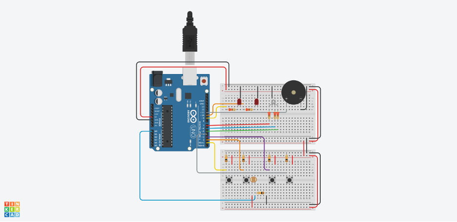
Arduino Prototyping in Tinkercad
Arduino Physical Circuit (Processing and Final Setup):
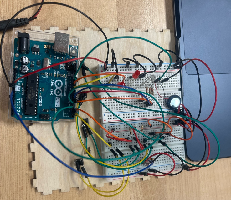
Arduino Physical Circuit Setup Before Adding 5V Battery
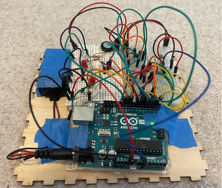
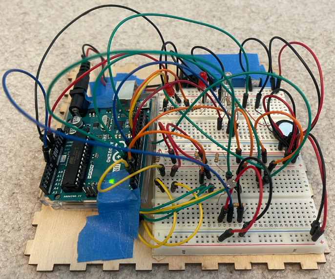
Arduino Physical Circuit Setup
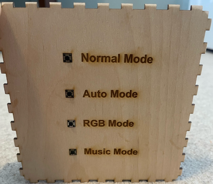
The Other Side of Laser Cut Wood Box showing 4 Modes & Buttons for User to Control
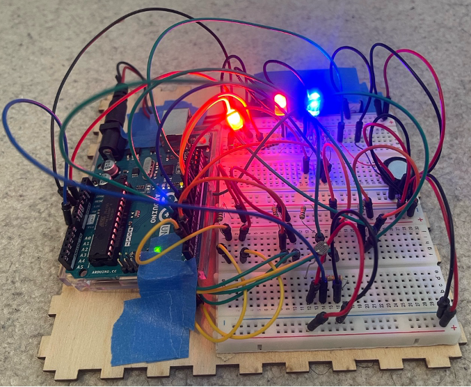
Arduino Physical Circuit Setup After all LEDs Have Been Illuminated
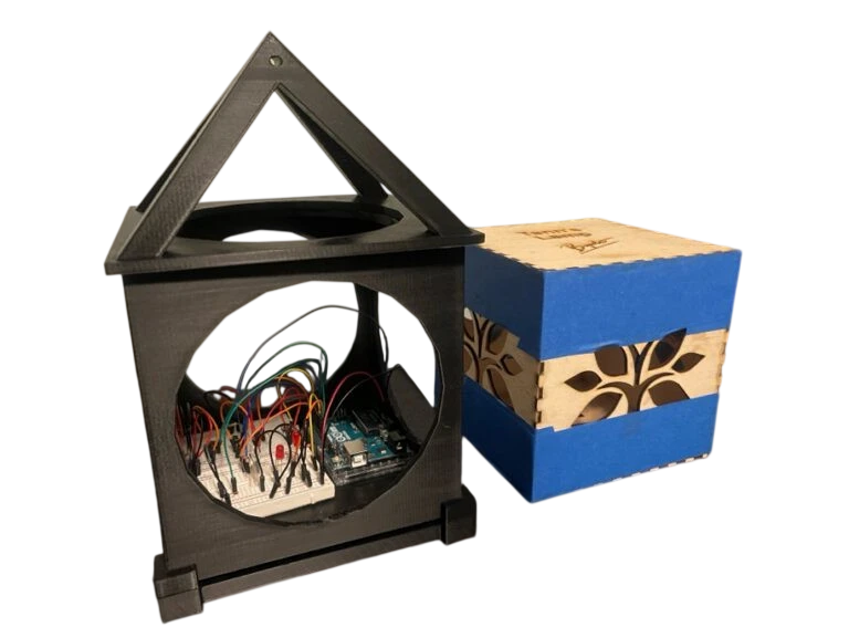
Outcome of All Elements Before Assembly
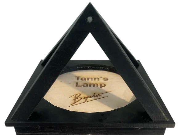
Combined Outcome of All Elements After Assembly (Top View)
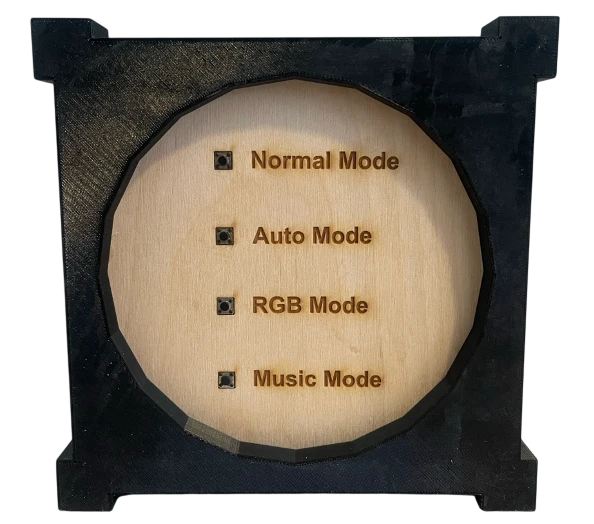
Combined Outcome of All Elements After Assembly (Bottom View)
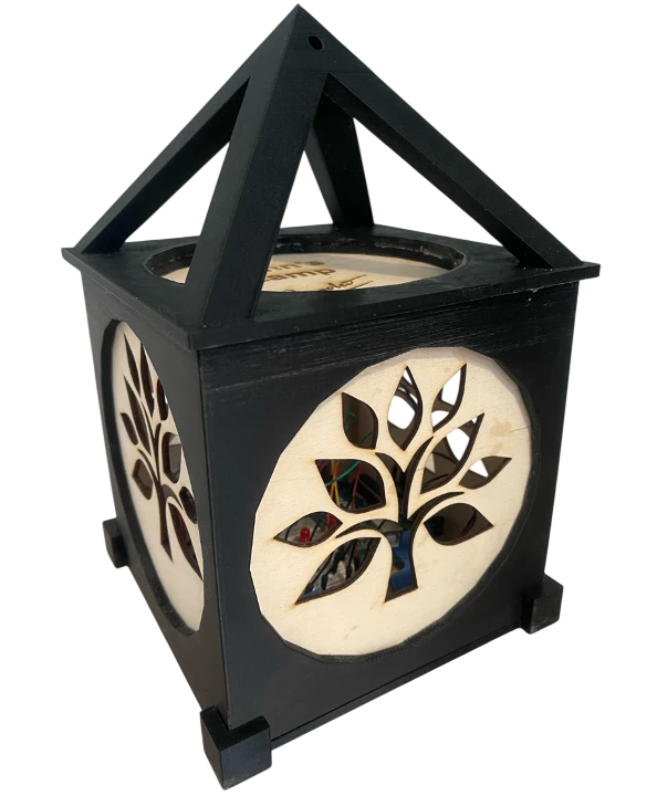
Combined Outcome of All Elements After Assembly (Side View)
In Conclusion
The RGB Lamp Box project successfully integrates 3D printing, laser cutting, and Arduino-based electronics into a single functional and visually engaging product. By designing and fabricating the lamp’s frame and enclosure, programming RGB LEDs and a buzzer, and prototyping both virtually in Tinkercad and physically on a breadboard, the project demonstrates a full engineering workflow from concept to final assembly. This work not only highlights the potential of combining digital fabrication with embedded systems, but also provides a strong foundation for future enhancements such as additional lighting modes, smarter interactivity, or integration with external sensors and controls.
Download the Full Research Paper
Get the full PDF for technical specs, design files, and Arduino code for this lamp.